The ER-32 and ER-64 electron Kilowatt-Hour (kWh) metering system is designed to submeter electric use in multifamily apartment and condominium projects. The ER-32 and ER-64 models are designed to meter 120/240V single-phase and 120/208V two and three-phase electric panels. These systems feature automated reading via telephone modem and are designed to meet ANSI C12.16-1991 accuracy standards.
The ER-32 and Er-64 models employ remote current transformer sensing elements installed at each electrical panel to be metered. All electronics are installed remote from the metered electrical panels and use common voltage input for each group of electrical panels. The system is most effective for 100 or more electrical panels and is capable of metering the excess of 1,000 panels per system.
The kWh computing module is a proprietary design which digitally calculates electric power in kilowatts and electric energy in kilowatt hours in real time.
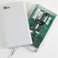
kWh Computing Module:
The kWh computing module is designed as a two or three board set to accommodate a maximum of 32 (ER-32) or 64 (ER-64) current transformer inputs respectively. The design meets ANSI C12.16-1991 standards.
Voltage inputs to each module are 120 V AC for one to three phases and are obtained typically from a common disconnect panel or transformer serving a group of electrical panels. Current inputs to each module (64 maximum) are low voltage (< 2 V AC) outputs from individual UL recognized current transformers installed at each electrical panel to be metered. Voltage inputs are hard wired to precision UL recognized voltage transformers while current inputs are terminated on quick-disconnect Panduit connectors mounted on interconnect boards.
The microprocessor kWh computing modules calculates Power = V I in real time for up to 64 current inputs and for one to three voltage phase inputs and then integrates power in real time to determine electrical consumption in kWh.
Provisions have been made in the design to allow field (or laboratory) testing and calibration of each input. Typically a JEM TEC SC-10 or SC-30 portable standard is used while the ER-32 and ER-64 is placed in a X.001 kWh test mode to enable a rapid test of kWh registration.
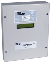
In addition to the computing module, each meter module contains a power isolation transformer for 28 V AC input power, a 6 V NiCad battery (1 ampere-hour minimum) for temporary power interruptions and a 12”w x18”h x 6”d NEMA 3R rain tight enclosure. All electronics are industry standard industrial grade including an Intel 80C31 microprocessor. Each module is designed for either interior or exterior installation.
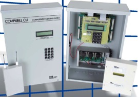
Central Collector/Display Unit:
Each kWh metering system includes a central collector/display unit with modem. The function of the central unit is to communicate with each kWh module (normal read cycle of once/10 minutes) and upload metered kWh readings that are then stored in the central unit for display or modem transfer to a remote IBM PC.
Each central collector includes a keyboard/display board and 2,400 or 14,400 baud modem. Each resident unit electrical kWh reading can be read from the display at any time. In addition, various system diagnostics and tests can be run from the central unit keyboard/display. Each central unit contains four (4) sets of dual optically isolated communication circuits for data transfer to/from each of four (4) groups of kWh modules. kWh modules are installed in a daisy-chain configuration. The central unit is housed in a 12’w x 18”h x 6”d NEMA 3 enclosure.
Remote kWh Reading:
The ER-32 and ER-64 Systems are designed for remote reading via IBM PC compatible equipment operating on dialing software under DOS 6.0. Standard business telephone lines are used to connect to the central unit modem and operation is at 2,400 or 14,000 baud.
The dialing software is designed to manually or automatically call multiple ER-32 and ER-64 installations and upload kWh readings stored in the central unit memory. The dialing software also contains various diagnostics to determine system or module failure within 24 hours of occurrence.
Power Supplies and Interconnecting Wiring:
The ER-32 and ER-64 are designed for installation in either multi-story residential buildings or in mult-building garden style residential projects.
Operating power for all ER-32 and ER-64 modules is supplied from a power limited (for safety) 28 VAC power transformer co-located with the central collector/display unit. Each module is provided with NiCad battery back-up for short (1 to 4 hour) power interruptions. Self-powered remote alarms are provided on site for audible warning if the power source is turned off. Non-volatile memory installed in each microprocessor kWh computing modules provides long term (multi year) data storage for more serious power interruptions.
All signal (current transformer) and communication wiring external to the central unit and meter modules is via 22 gauge telephone cable (interior, burial, or aerial). Typically interior cable is used within each building or for each floor of a multi-level building to connect current transformers to their respective meter module. Communication wiring from the central unit to the first set of meter modules and from one meter module to another is via two-pair aerial or burial cable. Primary 28 V AC power is typically run via 16 gauge single pair power cable.
ER 32/64 Electronic KWHR Submetering System Specifications
Dimensions: 12” X 18” X 6” Enclosure
Power Requirement: 12 Volt AC Operating Power
Voltage Input Configuration: 2, 3, 4 Wire Configurations
Voltage Ratings: 120; 12 / 240; 120/208
Current Range: 20 Amps Per Element
Frequency: 50 / 60 Hz
Accuracy: Certified to ANSI C12.1 & C 12.16 (National Accuracy Standards)
Temperature Range: -4 to 140º Operational Temperature Range
Input Capacity: 64 Inputs Per Module; 40 Modules Per System
Humidity: 0 - 95% Non Condensing
Display: 2 Line / 20 Character LCD Displays Increments to 1 Watt-hour
Installation Options: Indoor or Outdoor
Current Sensors: IMS Type 32410-BR1; UL Listed; 0-2 Volt A/C Output ANSI C12.1 & C12.16 Accuracy Standards 600 Volt Insulation Class; Split Sound Care
Additional Features: 6 Volt Nicad Back Up Battery
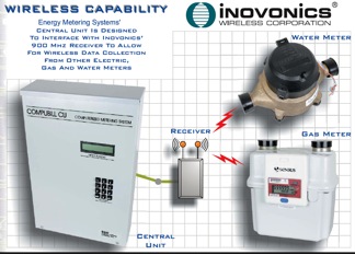
Wireless Features: Integrated Inovonics FA-403 Receiver Allows for Remotely Reading of Wireless Meters
Communications: On Board 96k Modem
Safety: Underwriters Laboratory Listed for Safety